

How does the turns ratio affect CT transformers?
Hey there! As a supplier of CT PT Transformers, I've seen firsthand how the turns ratio can have a huge impact on current transformers (CTs). In this blog post, I'll break down what the turns ratio is, how it affects CT transformers, and why it's crucial for you to understand these concepts as a potential buyer.
What is the Turns Ratio?
Let's start with the basics. The turns ratio in a CT transformer is the ratio of the number of turns in the secondary winding to the number of turns in the primary winding. It's usually represented as Ns/Np, where Ns is the number of turns in the secondary winding and Np is the number of turns in the primary winding.
For example, if a CT has a turns ratio of 100:1, it means there are 100 turns in the secondary winding for every 1 turn in the primary winding. This ratio is super important because it determines how the CT will transform the current from the primary side to the secondary side.
How the Turns Ratio Affects Current Transformation
The main job of a CT is to step down the high current in the primary circuit to a lower, more manageable current in the secondary circuit. This lower current is then used for metering, protection, or control purposes. The turns ratio plays a key role in this process.
Current Scaling
The turns ratio directly affects the relationship between the primary current (Ip) and the secondary current (Is). According to the basic principle of transformers, the product of the primary current and the number of primary turns is equal to the product of the secondary current and the number of secondary turns. Mathematically, this is expressed as Ip * Np = Is * Ns.
Rearranging this equation gives us Is = Ip * (Np/Ns). So, if you have a CT with a turns ratio of 100:1 and a primary current of 1000 A, the secondary current will be 1000 A * (1/100) = 10 A. This shows that the turns ratio allows us to scale down the high primary current to a more usable value on the secondary side.
Accuracy
The turns ratio also has a significant impact on the accuracy of the CT. In an ideal world, the turns ratio would be exact, and the relationship between the primary and secondary currents would follow the equation perfectly. However, in real-world scenarios, there are always some losses and inaccuracies.
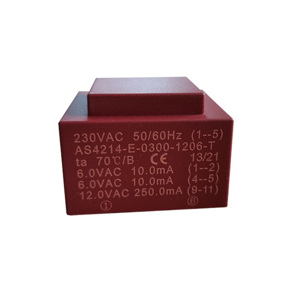

A well-designed CT with a precise turns ratio will provide more accurate current measurement. If the turns ratio is off, it can lead to errors in metering and protection systems. For example, if the actual turns ratio is different from the rated turns ratio, the measured current on the secondary side will not accurately represent the primary current. This can result in incorrect billing for electricity consumption or improper operation of protective relays.
Burden Capacity
The burden capacity of a CT refers to the maximum load that can be connected to the secondary winding without causing significant errors in the current measurement. The turns ratio affects the burden capacity because it determines the amount of current flowing in the secondary circuit.
A CT with a higher turns ratio will have a lower secondary current for a given primary current. This means it can handle a higher burden (load) on the secondary side without overloading. On the other hand, a CT with a lower turns ratio will have a higher secondary current, which limits the burden it can support.
Practical Considerations for Choosing the Right Turns Ratio
When selecting a CT transformer for your application, choosing the right turns ratio is crucial. Here are some practical considerations to keep in mind:
Load Requirements
First and foremost, you need to consider the load requirements of your metering, protection, or control system. Determine the maximum primary current that the CT will need to handle and the desired secondary current for your equipment. Based on these values, you can calculate the appropriate turns ratio.
For example, if your metering equipment is designed to work with a secondary current of 5 A and the maximum primary current in your circuit is 500 A, you'll need a CT with a turns ratio of 100:1 (500 A / 5 A = 100).
Accuracy Class
The accuracy class of a CT indicates the maximum allowable error in the current measurement. Different applications have different accuracy requirements. For example, metering applications typically require higher accuracy than protection applications.
When choosing a turns ratio, make sure to select a CT with an accuracy class that meets your specific needs. A higher accuracy class usually comes at a higher cost, so you need to balance the accuracy requirements with your budget.
Burden Rating
As mentioned earlier, the burden rating of a CT is an important factor to consider. Make sure the CT you choose can handle the burden (load) of your secondary circuit. If the burden is too high, it can cause errors in the current measurement and even damage the CT.
Related Products and Resources
If you're interested in learning more about potential transformers (PTs) and their applications, check out these useful resources:
- Types Of Potential Transformer
- Potential Transformers for Metering
- PT Potential Transformer
- CT and PT Transformer
- CT PT Transformer
Conclusion
In conclusion, the turns ratio is a critical factor that affects the performance of CT transformers. It determines how the current is scaled from the primary side to the secondary side, impacts the accuracy of the current measurement, and influences the burden capacity of the CT.
When choosing a CT transformer, it's essential to carefully consider the turns ratio based on your specific application requirements, including load requirements, accuracy class, and burden rating. By understanding how the turns ratio works and its implications, you can make an informed decision and select the right CT for your needs.
If you're in the market for high-quality CT PT transformers, we're here to help. We offer a wide range of transformers with different turns ratios and specifications to meet your diverse requirements. Contact us today to discuss your needs and start a procurement negotiation.
References
- Electric Machinery Fundamentals, Stephen J. Chapman
- Power System Protection and Switchgear, J. C. Das